

It's day 30 of the 30 Day Map Challenge, the last one, and today's theme is pen and paper.
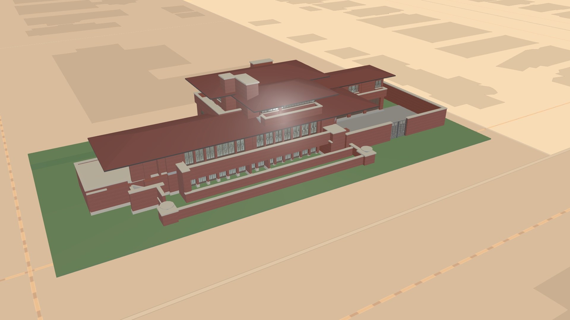
I think the idea is to draw a map by hand. I've taken a slightly different route: start from drawings somebody else made by hand, and see how far they can be taken. Today's map is the Robie House in Chicago, designed by Frank Lloyd Wright in 1908 and finished in 1910. Every wall, window and chair in it comes from fourteen sheets of ink drawings, most of them made in 1963, and it stands on the map where the real house stands.
Drag to look around. Use the control on the map to switch the roofs and floors off one at a time, and hover over any part to see what it is.
The drawings
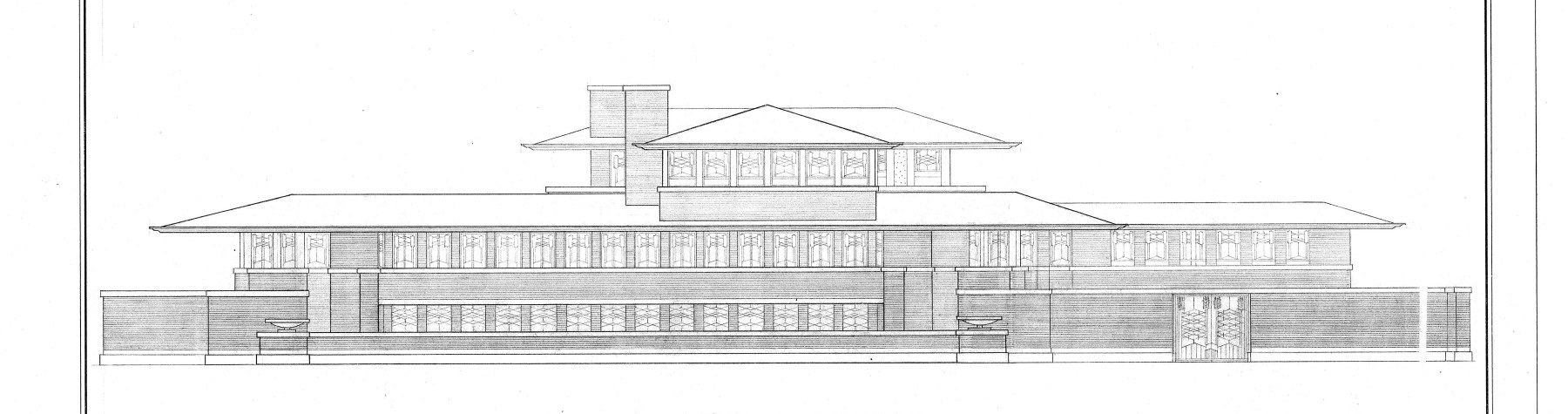
In the summer of 1963 a team from the Historic American Buildings Survey measured the Robie House and drew it in ink: three floor plans, a section, four elevations, the fireplace, the window glass and the furniture. The survey was run by the US National Park Service, so the drawings are in the public domain, and the Library of Congress keeps them as survey HABS IL-1005.
They are beautiful things. Every course of the long, thin Roman brick is ruled by hand, and the walls on the plans are filled with fine diagonal hatching. That hatching turned out to be the key to the whole job.
From ink to a model
I did not draw the model. I worked with Claude, Anthropic's AI model, and gave it the scanned sheets and one instruction: build what the drawings show.
- Walls from the hatching. On the plans, brick walls are hatched and everything else is left white. Claude wrote a small program that finds the hatched shapes on each floor plan and traces them, which gave the brick walls and piers of all three floors.
- Scale from one dimension. The ground floor plan carries an overall dimension of 161 feet 6 inches. Measuring that line on the scan gives the scale of every sheet.
- Heights from the section. The floor levels, ceilings, eaves and chimney tops are read off the long section and the fireplace drawings.
- Windows from the gaps. Wherever the hatched wall stops along an outside wall there is a window or a door, so every gap gets an oak frame and leaded glass.
- Furniture from its own sheets. The dining chairs with their tall slatted backs, the living room chairs, a footstool, a dresser and a bed are each drawn to scale, so they are in the model at their drawn sizes.
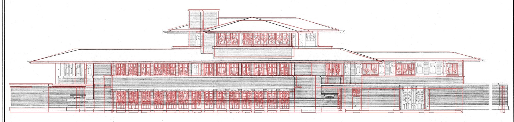
Then it checked its own work the way a surveyor would: it drew each side of the model at the scale of the drawings and laid it over the 1963 elevation. Where the red lines missed the ink, something was wrong. The first pass found a roof 3 feet too deep and a chimney that was missing altogether.
The result is not a shell. It is a building information model (BIM): about 650 separate parts on five levels, each one named, typed as a wall, window, stair, roof or chair, and tagged with the sheet it was read from.
Taking it apart
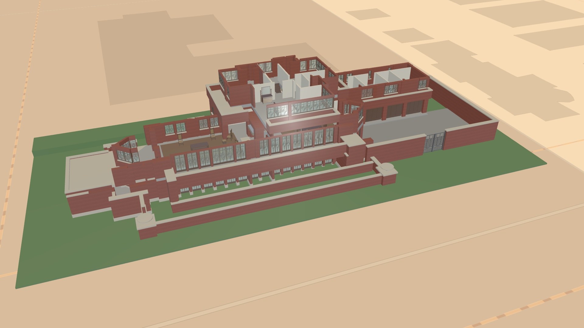
Because the model keeps its parts, the map can take it apart. Switch off the roofs and you are looking into the bedrooms. Switch off the third floor and the main floor appears as Wright planned it: one long room, with the living room and the dining room separated only by the fireplace. Take that away and you reach the billiard room and playroom at ground level.
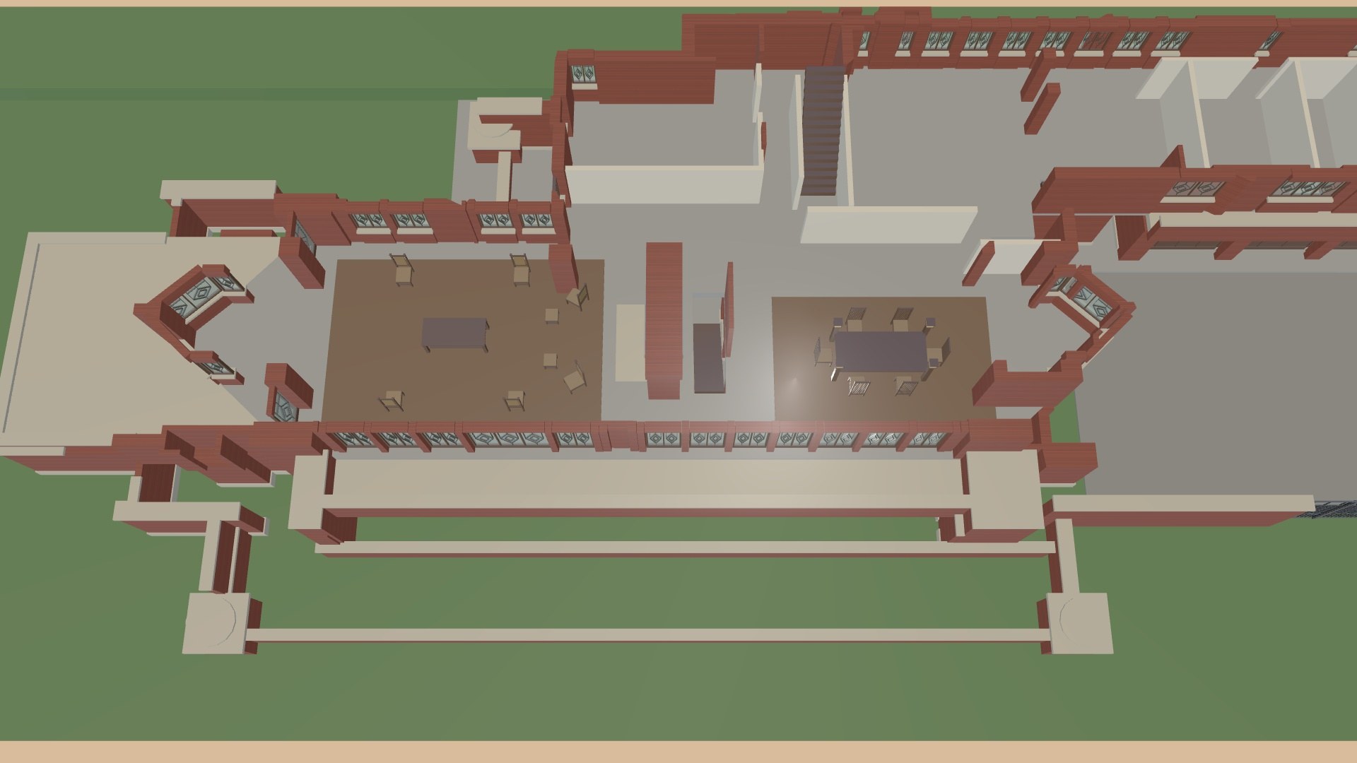
Seen from above with the upper floors removed, the model is the 1963 floor plan again, this time in three dimensions and in the right place on the Earth.
Built through the Icon Map MCP server
The map was put together without opening the editor. Icon Map has a Model Context Protocol (MCP) server, which lets an AI assistant work with Icon Map directly: read the authoring guide, search the catalog, check a map against the schema and save it to Fabric.
For this map the assistant:
- converted the model with the same converter the Icon Map editor uses, which keeps the part tree, the colors and the glass,
- chose the basemap and the opening view,
- wrote the BIM layer, placed at the position of the real house,
- checked the whole map against the Icon Map schema, and
- created the map in my Fabric workspace.
I opened it in Fabric to look at the result, and sent back screenshots of what was wrong: a gap under the third floor, a wall through a staircase, missing capping stones. Each one was fixed in the model's own recipe and the model was rebuilt. One of them was not a fault in the model at all. The brick courses ran up the walls instead of along them, which turned out to be a bug in our converter, so that is now fixed for everybody.
How accurate is it?
The model shows the house as the 1963 drawings show it, including the parts the survey marked as a conjectural restoration, such as the walls of the garage court. It is not a survey of the house as it stands today after its restoration.
The outside agrees with the four drawn elevations to about a foot.
The window glass is simplified. Wright designed different patterns for different rooms; the model uses one pattern of chevrons and diamonds, based on the survey's drawings, in every window.
The brick, stone and tile are plain colors with ruled courses, not photographs of the real materials.
The dining table, the living room table and the billiard table are not in the survey, so they are plain stand-ins and are marked as such in the model.
The house is placed by fitting its roofs to an aerial photograph, not from a land survey, so it may be a meter or so out.
Credits
Model built from the Historic American Buildings Survey drawings of the Frederick C. Robie House, HABS IL-1005, HABS Chicago Project 1963, Library of Congress, Prints and Photographs Division. Basemap © IconMap, © OpenStreetMap contributors.